Difference between revisions of "CyberBully"
(→Cyber Bully) |
(→Cyber Bully) |
||
| Line 20: | Line 20: | ||
<li> Rotating Hands - https://ccrma.stanford.edu/wiki/File:ErichPeske3.png </li> | <li> Rotating Hands - https://ccrma.stanford.edu/wiki/File:ErichPeske3.png </li> | ||
<li> Filter Glass Sounds - https://ccrma.stanford.edu/wiki/File:Gabriele_Sketch_2.jpg</li> | <li> Filter Glass Sounds - https://ccrma.stanford.edu/wiki/File:Gabriele_Sketch_2.jpg</li> | ||
| − | <li> Guitar Talkbox - https://ccrma.stanford.edu/wiki/ | + | <li> Guitar Talkbox - https://ccrma.stanford.edu/wiki/File:Talkbox.jpg</li> |
</ul> | </ul> | ||
Revision as of 11:06, 13 November 2013
Contents
Cyber Bully
Micah Arvey
Rooney Pitchford
Zach Saraf
Similar products:
- Atoner 4ms pedals http://www.youtube.com/watch?v=IIwP3_YZEYQ&feature=relmfu
- WMD Geiger Counter http://www.youtube.com/watch?v=4A7VFxIBj84
Similar on Wiki:
- Ipad Fun - https://ccrma.stanford.edu/wiki/File:IMG_2016.jpg
- Guitar Buttons - https://ccrma.stanford.edu/wiki/File:EliotKermit1.jpg
- Rotating Hands - https://ccrma.stanford.edu/wiki/File:ErichPeske3.png
- Filter Glass Sounds - https://ccrma.stanford.edu/wiki/File:Gabriele_Sketch_2.jpg
- Guitar Talkbox - https://ccrma.stanford.edu/wiki/File:Talkbox.jpg
Pics so far:
5) Three lists:
Minimal viable product:
-
Trackball volume controller
Motion in the ball in a given direction increases or decreases volume
- In x direction, volume is affected permanently (position)
- In y direction, volume is affected temporarily (according to acceleration)
Want to have done by the final deadline
- add delay, distortion, way, flanger
- toggle button to switch through effects
Things to do with unlimited time:
- Get rid of the computer. Make a fully functioning box, pre-programmed effects that cannot be changed
- Add the ability to affect the effect (to alter the parameters of an effect setting rather than the level of the effect)
5b) Elevator Pitch
The Guitar CyberBully effect ball offers a new level of player control to the world of guitar effects pedals. Digital effects alter the signal based on the velocity of the trackball in any direction. In one setting, spinning the ball to the left and right may lower and raise volume, while movement in the vertical direction would distort the signal, only as long as the ball spins. Toggle controls allow for customized sound design across multiple effects settings.
Materials:
- Trackball - maybe not check?
- Arduino
- enclosure
- misc. electronics
Extras:
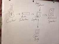
- Digital audio interface
- 1/4" instrument cable
- Laptop/Sound design software
Steps to realize minimal viable product:
- 1. Find the right ball.
- 2. Take apart ball and reassemble with function in mind.
- 3. Design effect programming.
- 4. For construction, we need to know the specifics of our setup. For every button we need that won't be covered by the USB trackball, we will have to program the Arduino to do the job instead.
Update: November 10
Materials for the total concept:
- 1. Trackball
- 2. 4 latching footswitches
- 3. 1 LED on/off display light
- 4. Beagle Board
- 5. 1 2-digit LED output number display
- 6. 3 knobs/pots, linear taper ---> we must decide which size!
Functional update:
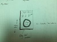
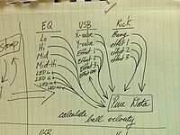
- As it stands, the machine has one trackball, four buttons, and three knobs. The trackball controls the level of each effect (in each axis). When the ball is not moving, the default effect level is determined by the "default" knobs, one for each axis. The middle knob is a general volume control knob.
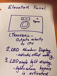
- There are four buttons. The "auxiliary" knob has a function designed specifically for each effect setting. This will enact a kind of "bang" effect, rather than a continuous one. The "bypass" button shuts off the effect and dries the signal. When bypass is activated, the LED display light labeled accordingly is lit up. The "toggle" button rotates through the effect settings (which come packaged with two axes). The number indicating the current setting is displayed on the LED number display above the trackball.
Update: November 12: Design Ready to Implement
We hope to have a working machine by tomorrow or the next day. We have pots and knobs for testing. We still have to work out the function of the fourth button. We also need to work out the input/output systems. We decided we want both the input and output to be 1/4" jacks. The BeagleBoard has an 1/8" output which can be converted to 1/4", and it also has an input which we hope can be used without an interface for direct input from the instrument. This will take some more ordering of parts. We will figure out that system and the needed parts when we meet later today.
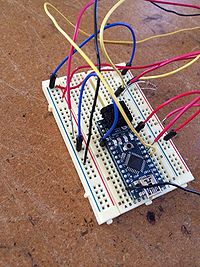
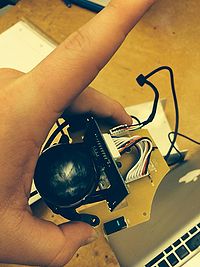
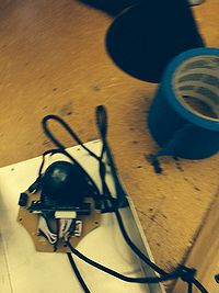
Update, November 13: with pictures
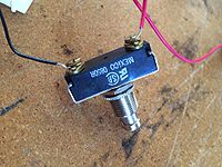
We got our buttons working with the Arduino. We are using single pole, single throw push switches to send bang messages to the computer. Though I thought we did before, we do not need latching switches. Every button's function needs a momentary switch, especially the toggle.
We used potentiometers and knobs to get input for the dial settings. As of now, we can receive bang messages from the momentary switches through the digital pins on the Arduino, while we take analog data from the pots.
We are currently skipping the BeagleBoard because the disk hasn't been imaged. When the time comes, we need to run the Arduino from the BeagleBoard, but at the moment for design ease we are using laptops.
IMPORTANT STEP TO BE COVERED. INPUTS/OUTPUTS We have committed to using 1/4" inputs and outputs so that the machine can take a guitar with no interface and put out directly to an amplifier. This means we won't have to design guitar tones (for regular play) on the computer.
The machine also has an ethernet port, so that designers at home can design their own sounds and throw them on.

