DOCUMENTATION


After much deliberation, levitating magnets guided by clear plastic rods were implemented to capture the displacement compression using Hall Effect sensors (a magnetic field sensor). Priced at around $1, Hall Effect sensors provide a cheap and relatively easy method for sensing the required vertical axis.  Additionally, cheap generic square magnets were used (three/rod). As seen in the figure to the left, two magnets are fastened to the underside of the sequencer—one directly attached to the sequencer base and one directly attached to the standing vertical rod.  Opposite polarity fastens the rod to the sequencer base while simultaneously increasing the Hall Effect sensitivity and levitating force.  The floating magnetic above (guided by the rod) is set in equilibrium nearly 2 cm above the base providing a respectable clearance to measure up to three individual cubes.  As each cube is placed downward onto the floating magnet, a new equilibrium point is found closer to the base of the sequencer. This change in distance is measured via the Hall Effect sensor, which in turn outputs an increased analog voltage.  This voltage level is sampled or discretized using an analog-to-digital converter onboard a microcontroller. 


Housed within a 20x16x6 inch Plexiglas black box, a total of 64 clear plastic rods, 64 Hall Effect sensors, 64 light-emitting diodes (LEDs), 1 Atmel AVR ATMega 32 microcontroller, and numerous multiplexers are used for the general design.  All analog-to-digital (Hall Effect sensors) conversion is handled via the microcontroller with little extraneous circuitry. 

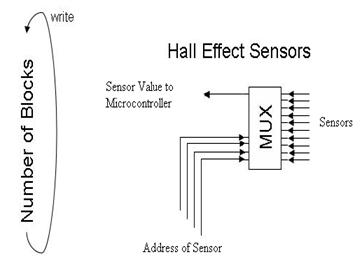
As seen in the figure to the left, to handle the large input/output sensing scheme, however, numerous multiplexers are used to map multiple Hall Effect sensors onto a single analog-to-digital pin on the microcontroller (totaling four A/D pins for the 64 continuous sensors).  Similarly, multiplexers are also used for the LED output control, sending a simple voltage on/off signal.  


HOW ARE WE INPUTTING 64 SENSORS USING SO FEW A/D CONVERTERS?
HOW ARE WE SENSING THE CUBES?
WHAT SOFTWARE?


The microcontroller can easily connect to a personal computer via a Universal Serial Bus (USB) connection, programmed in the C programming language to input the sensing data, output the lighting data, and communicate to third-party audio applications using Open Sound Control (OSC) messages such as Pure Data (Pd).  See  AVR-CCRMA Wiki [http://cm-wiki.stanford.edu/wiki/AVR].

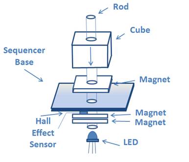
From the analog-to-digital conversion of the continuous sensor voltage levels, a maximum-likelihood threshold estimation is used to resolve the number of blocks/rod (i.e. 0, 1, 2, or 3).  Large variability in sensors and magnet strength require an initial calibration phase, measuring the mean displacement per number of cubes.  Once calibrated, the sequencer enters a ready state mode and begins to sample the sensor data and establish two-way communication to a personal computer.

The necessary information is then sent to Pd via OSC into a sequencer patch.  The sequencer patch synchronizes the commands on light and sound to a beats per minute (BPM) rate and quantization ratio controlled by the user (the baseline quantization count is sent to the microcontroller at the respective tempo).  Additionally, OSC message data rate is reduced for maximum performance by only sending changes in the number of block.


HOME


nbryan [at] stanford.edu         steinunn [at] stanford.edu         hbursk [at] stanford.edu

center for computer Research in music and acoustics (CCRMA)
Stanford university, California USA