Lab 3: Sensors and Physical Interface Design
The goal of this lab is to control Faust synthesizers with sensors connected to the Teensy. Various mapping strategies are also introduced.
Electronic Basics
- Review this brief introduction to electronics on the CCRMA Wiki.
Sensors and Teensy Basics
- A wide range of sensors act as resistors (e.g., Force Sensitive Resistors, photoresistors, SoftPots, flex sensors, etc.) and can be used to dynamically change the amount of current circulating in a circuit.
- Microcontrollers such as the Teensy can be used to digitize the signal delivered by a sensor in a circuit (which is the same as measuring the amount of current in the system at regular time intervals).
- Briefly review the Teensy 4.0 pins map (scroll down to the “Pins” section of this page). You’ll have to refer to it relatively often in this lab so make sure to save it somewhere.
- Connect your Teensy to your breadboard as follows (GND to the blue/black - strip and 3.3v to the red + strip):
- WARNING: do not use the “Vin” pin (top right pin) that could potentially fry your Teensy. You want to use the 3.3V pin (third pin from the top on the right hand side) for this task.

- In the breadboard distributed with your kit, power pins (2 leftmost and 2 rightmost black/red strips) are connected in groups of 5 pins.
- Make a circuit connecting a photoresistor or a FSR (they work the same way) to the analog input 0 (A0) of the Teensy:


- The FSR in your kit is smaller than the one shown on the picture here. FSRs and photoresistors don’t have a polarity so you don’t need to respect a specific orientation to plug them to the breadboard.
- Notice the use of a 10k pull down resistor which is used to stabilize power readings on the A0 pin of your Teensy.
- Let’s now retrieve the photoresistor/FSR signal on your computer and plot it in the debugger! First, upload this program to your Teensy:
void setup() {
  Serial.begin(9600); // initializing serial port
}

void loop() {
  int sensorValue = analogRead(A0); // retrieving sensor value on Analog pin 0
  Serial.println(sensorValue);
  delay(30); // wait for 30ms
}- Note that we pause the loop for 30ms at every cycle to not overload the serial output.
- Open the serial debugger (the loop icon on the top right corner of the Arduino software) and make sure that your system is working by covering the photoresistor with your hand or by squeezing the FSR. Note that the output value is a 10 bits integer (value between 0 and 1023). If nothing is plotted, make sure that the right port has been selected in
Tools/Port - We now want to control the parameter of a Faust-generated sound processing object with the photoresistor/FSR. Reuse the Faust sawtooth oscillator program from the Faust-Teensy tutorial (https://faustdoc.grame.fr/tutorials/teensy/#band-limited-sawtooth-oscillator-on-the-teensy), compile it as a Teensy audio object and import it your Arduino/Teensy program as such:
#include <Audio.h>
#include "FaustSawtooth.h"

FaustSawtooth faustSawtooth;
AudioOutputI2S out;
AudioControlSGTL5000 audioShield;
AudioConnection patchCord0(faustSawtooth,0,out,0);
AudioConnection patchCord1(faustSawtooth,0,out,1);

void setup() {
  AudioMemory(2);
  audioShield.enable();
  audioShield.volume(0.1);
}

void loop() {
  int sensorValue = analogRead(A0);
  float frequency = sensorValue + 50;
  faustSawtooth.setParamValue("freq",frequency);
}sensorValueis used to computefrequency(that’s what we call the “mapping”) which in this case will be a value between 50 and 1073Hz.- Shading the photoresistor/pressing on the FSR should now change the frequency of the generated sawtooth.
Exercise: Controlling Multiple Synth Parameters
- Try to use the FSR and the photoresistor together to add gain control to your synth.
- For that, you’ll have to integrate the photoresistor or the FSR (depending on your initial choice) to your circuit and plug it to one of the available analog inputs of the Teensy. Since the audio shield uses some of the pins of the Teensy, you should check which ones are actually “free” in the “Signals to Teensy” section of https://www.pjrc.com/store/teensy3_audio.html.
- Add a gain control parameter to the Faust program and control it with the potentiometer.
- Tip: adding a gain parameter will not allow you to control the amplitude of the generated sound linearly, for that you’ll have to square it. E.g.,:
g = hslider("amplitude",0.5,0,1,0.01)^2; Discrete Events
Looping Through Notes
The goal of this section is to make an instrument with the following behavior:
- it should loop through the notes of a simple melody,
- every time a button is pushed, a new note is triggered,
- when the button is not pressed, we hear no sound.
First, add a button to your circuit. The buttons provided in your kits have 4 pins (2 sets of 2 pins connected to each other). Place the button as follows on the breadboard:
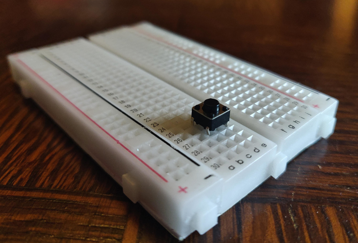
Then connect one of the 2 pins to power and the other pin to the digital input 0 of your Teensy. You should add a pull-down resistor to this pin too. Note that an analog input could have been used as in the previous examples, but since we’re retrieving a discrete signal it doesn’t really make sense.

- Compile the following program in the Faust Web IDE for the Teensy (you can give the name you want, in the next steps of the lab we kept the same name as before:
FaustSawtooth):
import("stdfaust.lib");
freq = hslider("pitch",60,0,127,1) : ba.midikey2hz;
gate = button("gate");
process = os.sawtooth(freq)*gate;- Note that the frequency here is computed from a MIDI pitch number.
- On the Teensy side, run the following program:
#include <Audio.h>
#include "FaustSawtooth.h"

FaustSawtooth faustSawtooth;
AudioOutputI2S out;
AudioControlSGTL5000 audioShield;
AudioConnection patchCord0(faustSawtooth,0,out,0);
AudioConnection patchCord1(faustSawtooth,0,out,1);

int notes[] = {60,60,60,62,64,62,60,64,62,62,60}; // the melody
int cnt = 0; // index to loop through the notes
bool change = true; // did the note status changed?
bool on = false; // what is the note status?

void setup() {
  pinMode(0, INPUT); // configuring digital pin 0 as an input
  AudioMemory(2);
  audioShield.enable();
  audioShield.volume(0.1);
}

void loop() {
  if (digitalRead(0)) { // button is pressed
    if(!on) change = true; // did the status of the button changed
    on = true;
  }
  else {
    if(on) change = true; // did the status of the button change?
    on = false;
  }

  if(change){ // if the status of the button changed
    if(on){ // if the button is pressed
      faustSawtooth.setParamValue("gate",1);
      faustSawtooth.setParamValue("pitch",notes[cnt%11]);
      cnt++; // next note
    }
    else{
      faustSawtooth.setParamValue("gate",0);
    }
    change = false; // status changed
  }
}
Notes are saved in an integer array as MIDI note numbers. When digital pin 0 receives a signal, the on variable is set to true and vice versa. The change variable is used to make sure that we only send messages when necessary.
Exercise
Continuous parameters can be controlled in parallel of this button/looping mechanism. Add a lowpass filter to your sawtooth oscillator, e.g.,:
process = os.sawtooth(freq)*gate : fi.resonlp(ctFreq,5,0.5);and control the value of the cutoff frequency with the photoresistor or FSR on your circuit. Spend some time thinking about the mapping of the cutoff frequency: what works best in this context?
Hint:
The min and max functions are often useful when mapping a sound synthesis parameter to a sensor. For instance, you probably noticed that the photoresistor doesn’t “fully exploit” the 0-1023 range offered by the 10bits converter. A common practice is to normalize the sensor output so that you can fully take advantage of its range. For example, say that you see that the output range of your sensor is 500-900, you could normalize its output with something like:
normSens = min(1023,max(0,sens - 550)*3.3);Here subtracting 550 to the raw sensor output (sens) and then comparing that to 0 with max will make sure that the lowest value of the sensor is 0. Multiplying the result of this operation by 3.3 and comparing the result to 1023 with min will ensure that the highest value of the sensor is 1023.
Using the Other Sensors of Your Kit
You don’t have to do this section right away and you can jump directly to the assignment section at the bottom of this page if you wish. This section is meant to be used as a resource for your assignment and/or final project. If you have time, feel free to read through it though.
The other sensors in your kit require additional work to be used (e.g., soldering, use of specific libraries, etc.). Here, we provide you with some guidelines on how to use these sensors. These are just suggestions: this section doesn’t provide exhaustive information. Keep in mind that people in this field spend a lot of time finding tutorials on the web (Google is your friend). Also keep in mind that you might want to reuse these sensors: make sure that whatever you do here can be repurposed.
More generally, feel free to buy any sensor on the web for your projects. Sensors can be analog or digital, can work as resistors or not, etc. You’ll usually always be able to find a tutorial on how to use them with your Teensy. Remember that your Teensy works the same way as an Arduino so in some cases in might more judicious to do a search on the web for “thisSensor Arduino” instead of “thisSensor Teensy”, etc.
HC-SR04 Ultrasonic Distance Sensor
Your kit comes with an Ultrasonic Distance Sensor which measures the distance between the sensor and an object placed in front of it by emitting ultrasounds. Four wires need to be connected to this sensor: 2 for power and ground and 2 for controlling it/acquiring data. To use it with your Teensy, we suggest you to follow this tutorial: http://little-scale.blogspot.com/2020/06/teensy-36-with-hc-sr04-distance-sensor.html. It implies the use of a library: https://www.arduinolibraries.info/libraries/hcsr04 and of a couple of 10k resistors (part of your kit).
WARNING: this sensor operates at 5V (not 3.3V). It means that you’ll have to use the “Vin” pin of your Teensy to power it. Be extremely careful when doing so since you could fry your Teensy by plugging this pin directly to any other pin on the Teensy! The 10k resistors are used as a voltage divider here to make sure that the current sent to the Teensy from the sensor doesn’t exceed 3.3V.
Here is a wiring suggestion (following the tutorial above):


and some piece of code from the tutorial:
#include <HCSR04.h>

float data;

UltraSonicDistanceSensor distanceSensor(0,1);

void setup (){
  Serial.begin(9600);
}

void loop () {
  data = distanceSensor.measureDistanceCm();
  Serial.println(data);
  delay(100);
}
Potentiometer
Your kit comes with a set of linear rotary potentiometers. Wires need to be soldered to them in order to connect them to your breadboard. The easiest way to do this is to “sacrifice” some of your jumper wires by soldering them to the potentiometer.
First, hook up the three jumper wires to the potentiometer:

The color of the wires doesn’t matter. You can then solder them:

You should now be able to easily plug it to your breadboard. The leftmost and rightmost pin are for power (3.3V) and ground (flipping them will change the orientation of the potentiometer) and the center pin should be connected to an analog input of your Teensy.
Alternatively, if you don’t want to waste three of your jumper wires, you could cut small sections of stranded wire, strip them, and add solder to one of their end so that you can use them with a breadboard (as shown in the Accelerometer example).
Accelerometer
The accelerometer in your kit is a three axis analog accelerometer. Some soldering is required to use it. 2 wires should be used for power (3.3V) through the GND and VCC pins, and sensor values can be read with analog pins on your Teensy through the X, Y and Z pins on the accelerometer (i.e., one pin per axis).
You could use jumper wires as you did for the potentiometer or you could make your own wires using stranded wire. For that, cut 5 small wires and strip them on both ends using a sharp knife:

To strip the wires, place them on a flat surface and slowly rotate them with the blade of the knife on them. Then, pull the extra insolant out of the wire:

Then, pre-solder the two ends of each wire. Make sure to not put too much solder on the end that you’ll use on the breadboard:

Solder the other ends of the wires to the VCC, GND, X, Y, and Z pins of the accelerometer:

The color of the wires doesn’t matter (we did use 2 different colors for power and ground to differentiate them though).
Cut the extra end of the wire on the accelerometer using the wire cutters from your kit:

Finally, connect the accelerometer to the breadboard:

The X, Y, and Z pins should be connected to individual analog inputs of your Teensy.
Infrared Distance Sensor
The infrared distance sensor of your kit comes with a 3 wires cable:

To use it with a breadboard, you’ll have strip its ends and put some solder on them to make them solid (as in the accelerometer example). After this, you should be able to press the wires in the breadboard:
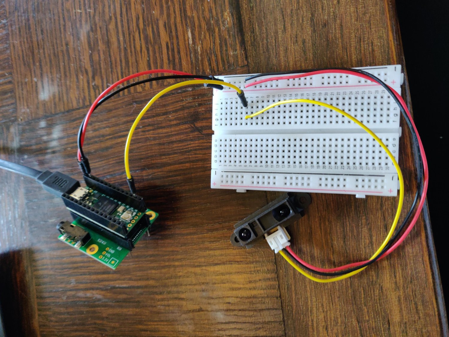
Like the Ultrasonic Distance Sensor, the infrared distance sensor needs to be powered with a 5V DC current. Hence, you should use the Vin 5V pin on the Teensy to power it.
Warning: read the warning sections of the Ultrasonic Distance Sensor since the same type of precautions need to be taken with this sensor.
Assignment (Due on Apr. 28, 2021)
- Design an instrument running on the Teensy combining a bunch of sensors and a sound synthesizer implemented in Faust.
- Feel free to explore the various sensors which are part of your kit.
- Your instrument should involve at least one discrete element (i.e., a button) and one continuous one (i.e., a potentiometer).
- Think about the mapping strategies you’ll be using on the sensors (e.g., Does it make percussive sounds? Are all the parameters linear as opposed to logarithmic, for example? Etc.).
- Make sure that your instrument is expressive, artful, beautiful, playable, etc. You could obviously fulfill the requirements for this assignment by using any of the code of this lab, but we expect more: be creative!
- Think about the form (vs. function) of your instrument. Feel free to wrap it into something, dress it, etc. Don’t be afraid to use duct tape for that.
- Make a demo video of your instrument. The content of this video is pretty open. The only requirements are that it should contain a short music statement, it shouldn’t be boring, and it shouldn’t exceed 1:30 mins.
- Post the video on YouTube and send the link to Doug and Romain along with the Faust code of your instrument by Apr. 28, 2021.
- Good luck and have fun!