 |
CCRMA Stanford UniversityMusic 250 HCI Technology: Controllerslab 5: communications (OSC) and more sensors |
| home schedule homework project labs materials resources |
In this lab we will be completing our understanding of the data path from sensor to sound. The data is contained in data protocol called OSC (Open Sound Control). This protocol, for our purposes, takes the place of midi. On the ATMega16, analog sensors are sampled by the A/D
converters, digital data by the I/O pins. Our program on
the AVR converts this sample data to the special OSC format and wraps
it into packets. These packets are sent from the AVR over the
serial bus to the computer. Pd is running on the computer, with a
patch window open which contains a 'dumpOSC' object. this object is
listening on the serial port for OSC messages, which it imports into
pd. you can then use the sensor data in pd any way you like to drive
synthesis objects.
referencesthe labCopy the lab5 folder to your 250a/labs folder, and uncompress it: Start up abc.pd: ..lab5/abc>pd abc.pdInside abc.pd you should see two analog values attached to
PORTA (A0 and A1) with ranges of [0..1023] displayed on the two
sliders. The four buttons on the AVRmini (if jumpered to PORTB)
show up as X in the four boxes (b/[1..4]). A counter (c/)
increments everytime all the values are updated.1. From lab3, you should have two continuous sensors to attach to A0 and A1. With "compute audio" checked, you should hear a sine wave whose frequency and amplitude are controlled by your two sensors. Adjust the range of your sensors for "best playability" (change reference resistors in the voltage divider or re-map in Pd). Report to the instructor with your values and methods of adjustment. 2. Try optical sensors. Here is a page-full at Digikey. This reflective object sensor (Honeywell's HOA1405-001) requires a 150-220 ohm resistor in series with the infrared LED Emitter, and a comparison resistor to create a voltage divider with the photo transistor. Instead of 10K on the Sensor, you might try 20K to give a better range. 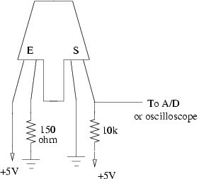 Also, you can make a beam-breaker by pointing an emitter (IR LED, Jameco 112168) at a Sensor (IR Phototransistor, Jameco 106526). Try 100 ohms in series with the LED and 47K for the Sensor "voltage divider". Circuits are here. 3. Try an alternative synthesizer in Pd and control it with your sensors. Try marimba~ or others from the Percolate library. Add other sensors (analog or digital), write code to read them, extend your OSC "address space" and route them with Pd to control your synthesizer. accel1. Compile and load accel.c with the included makefile (including the required Resets before and after yourmake load)2. Open the accel.pd patch in pd. Is there data coming from your avr into pd? 3. Step through the comments in the patch, taking a very close look at the patch. Answer the questions posed by the comments.
|