Experimental Wind Instruments
Adnan Marquez-Borbon - CCRMA
Rob Ernst - Cogswell Polytechnical College
This project began as a curious exploration of some unusual musical
possibilities for acoustic tubes.
It consists of two parts: one being the excitation of multiple tubes by
a single source and second,
the seamless introduction of electronic feedback into an acoustic tube.
Multiphonic Bass Clarinet (MBC)
Goal:
Our Goal was to make a multiphonic clarinet that could be used in a
live setting as a droning
instrument. In order to achieve multiple different pitches from a
single wind instrument,
we had to use multiple tubes of varying lengths that all protruded from
a single mouthpiece.
The goal was to make a drone that had some very interesting beating
created by the different
frequencies of each tube, so we cut the tubes according to the desired
frequencies.
The other thing we had to think about was that it is going to be played
in a live setting,
possibly simultaneously with a keyboard. So the instrument had to be
relatively light weight
and compact. Lastly, for amplification as well as greater sonic
versatility, we decided to add
small condenser microphones to the ends of each pipe, so that we could
plug it into a computer
interface and further manipulate, or just amplify and record the sound.
A cylindrical bore was chosen due to the facility it provides in
constructing an instrument.
After researching some of the dimensions of Bass Clarinets it was found
that the inner diameter
of the bore is approximately 0.92 inches and that the length of the
bore from mouthpiece to bell
lies around 42-43 inches (some sources state variations ranging from 37
to 51.9 in).
The lowest frequency of the instrument is a sounding D2 (73.42 Hz).
Using the formula for tubes closed on one side, fn = (2n-1)(v/4L), it
was proceeded to calculate
the length of the tubes based on the lowest frequency desired.
Materials:
- 1" PVC Pipe (10')
- 90 degree angle connectors (2)
- 90 degree T splitters (3)
- Bass clarinet mouthpiece, ligature and bass clarinet reeds (2 1/2)
- Small condenser mic capsules (4)
- Capacitors (4)
- Resistors (4)
- 9V batteries and connectors (4)
- 1/4 in phone plugs (4)
- Various wire
The inner diameter of the PVC pipe is close to our ideal bore diameter
and in practice,
the difference in diameter does not affect much of the acoustic
characteristics of the tube.
The Build:
The first thing we had to do was to figure out how long to cut the
piping to get our selected
frequencies. The frequencies we were shooting for were: 73.42 Hz (D2),
110.0 Hz (A2),
146.8 Hz (D3), and the last tube we wanted to be able to slide from
130.8 to 167.8 Hz (C3-E3).
In order to determine the length needed for each frequency we used the
formula: Fn = (2n-1) v/4L
With this formula we determined that the proper lengths for those
frequencies were:
1.17 m, 0.779 m, 0.584 m, and 0.656 m. But we could not just cut our
pipes to this length,
because we also needed to take into account the distance from the
mouthpiece to the beginning
of the sounding pipes. This distance would act as part of the pipe and
change the frequency.
So when we subtracted that distance our final numbers were 0.93 m,
0.619 m, 0.424 m, and 0.416 m.
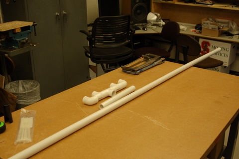
Then we measured our long pipe and started cutting. While we were at it
we also cut some 1 1/2 in
pieces of pipe to mate our angled connectors near the mouthpiece.
After cleaning up the edges all we had to do was simply put it
together. We attached the mouthpiece
and gave it a try. The first noticeable problem was that it was very
hard to make all four pipes
to sound at once. It takes a very focused breath and if you stray a
little from it the instrument
can squeak or only sound some of the pipes. After a little bit of
practice it started
to sound pretty good.
 pipes
pipes
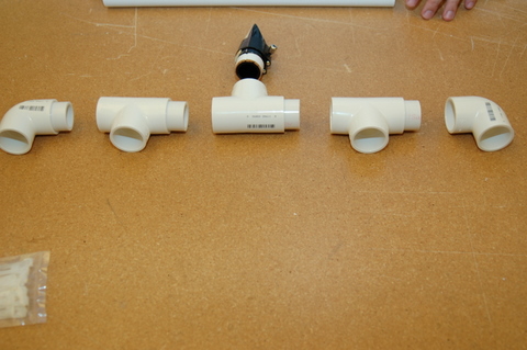 connectors
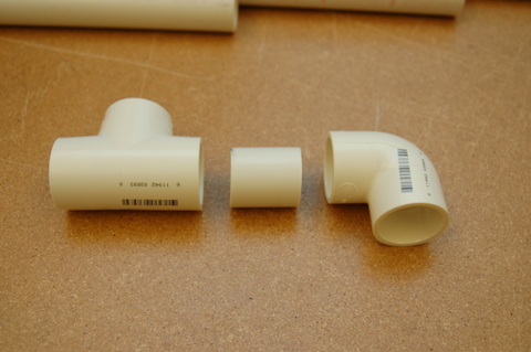 detail
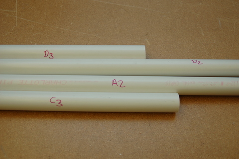 tube pitches
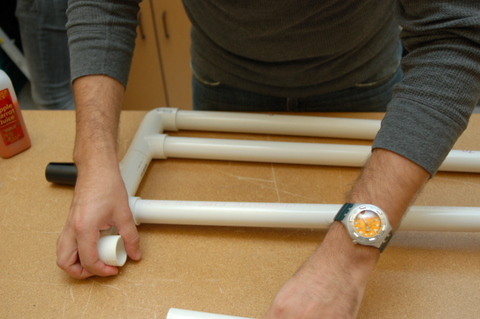 assembly
 finished MBC
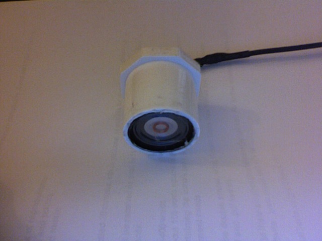
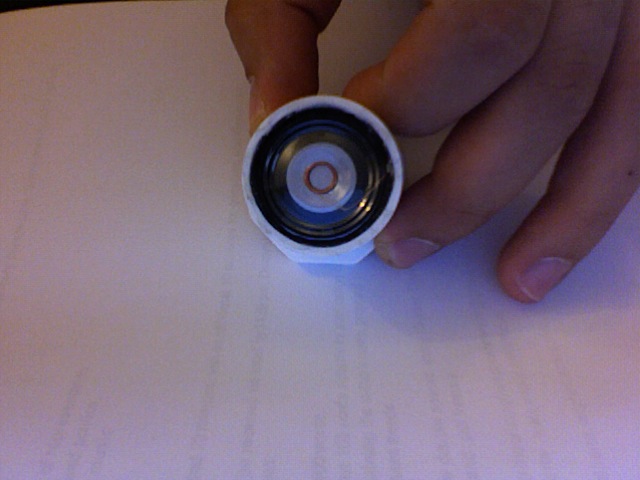
 microphone
 microphone
closeup
microphone
closeup
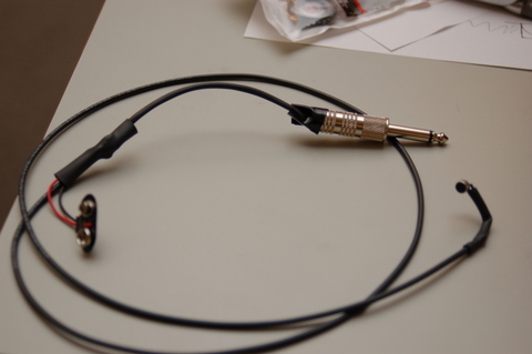
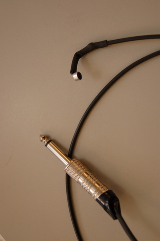
The last thing to do is to build four
microphones for each tube and mount them with zip ties.
I built a simple program in Pd
and
ChucK ,
as well as a graphic interface in
Processing
to use with
the instrument in a live performance setting. You can find them here:
MBC patches
Here's what the instrument sounds like:
MBC
with freeverb
MBC
with feedback delay network
Feedback Bass Clarinet (FB2C)
Goal:
To incorporate an electronic feedback system into an acoustic instrument.
Materials:
- 1" PVC Pipe (6')
- 90 degree T splitters (3)
- 1" PVC cap (1)
- Bass clarinet mouthpiece, ligature and bass clarinet reeds (2 1/2)
- Small condenser mic capsule (1)
- Capacitors (1)
- Resistors (1)
- 9V batteries and connectors (1)
- 1/4 in phone plugs (2)
- mini speaker (1)
- Various wire
The Build:
Make one
microphone of the previously mentioned type, and make the
mini speaker connection
by directly connected to a 1/4" mono plug (speaker (-) to ground and
(+) to signal).
This instrument is very straight-forward in its construction, however
the speaker must be
fixed into the T coupling in such a way that air leakage is avoided.
Otherwise, the instrument will
"speak" at the length were there leak lies in (which should be a higher
pitch than desired).
The mini-speaker is mounted on the inside of the cap. The inside
diameter had to be increased with
a dremel tool because the speaker was a bit too big. Then we drill and
hole at the back of the cap
so the speaker cables can go out. Once we have everything set, we hot
glue the inside of the cap
opening and mount the speaker. Finally, with the cables poking out of
the back of the cap, we hot glued
the hole and cables so we can have a seal and avoid any air leakage.
Finally, the driver is mounted on the side opposite to the tube so that
the sound coming from it is
has a direct path to the microphone. The mouthpiece will be put on the
mid coupling. The arrangement
is a bit odd, but otherwise getting feedback to occur will be a bit
more difficult.
 driver and cap
 driver
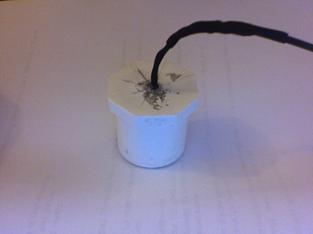 cap top view
 finished FB2C
A simple program in Pd and ChucK was written to be used with the
instrument.
Here they
are: FB2C
NOTE: After realizing that having the feedback loop go through the audio
interface produced some bad sounding digital clipping and that the
gain control was a bit difficult to control, an analog
mixer along with a SP-303 sampler we used instead.
An auxiliary output of the mixer is sent to the input of the sampler,
and the output of the sampler is sent to the aux return bus of the mixer.
Finally, one of the main outputs (or control room out) is sent to the driver
in the tube. Appropriate gain staging is done in order to achieve feedback.
Just make sure that the signal is not "on the red" if you plan on recording,
otherwise the signal will clip and it will not sound good at all.
Once we have feedback, we can put any effect we desire in the sampler.
In this case delay and pitch shifting tend to work quite well.
Other routing schemes were tested, but in the end the result was the
same.
Hear the instrument: WARNING! IT CAN GET VERY LOUD
FB2C
(6' pipe @ ~47 Hz)
FB2C
(16' pipe @ ~17.6 Hz)
adnanm[at]ccrma.stanford.edu
Last modified: 1 December 2008