Project: Homemade Ambisonic Microphone
History
Ambisonics is a few things. It refers to a 3 dimensional recording and playback technique which creates an Isotropic soundfield for listeners. It also refers to the recording and surround sound technology in which the isotropic soundfield is produced. Recording in Ambisonics requires a special microphone which records with a set isotropic polar pattern due to the way the combination of microphones are configured then encodes that signal known as an “A format” signal into ambisonic format known as “B format”. This encoding process used to have to be done in hardware and this project explores software encoding. The first soundfield microphone was developed by Michael Gerzon and company at Oxford University in the 1970's.
Process of Ambisonic Recordning and Playback
A format signal is recorded using ambisonic microphone. The signal is encoded into B-format using softare. The signal is mixed and decoded into B format by sofware and run into speaker arrays for specific wave summing and negating scenarioes to create “virtual sources”. This process is based on the following encoding formula developed by Gerzon and in use today in Soundfield microphones.
The Formula
W' = FLU+FRD+BLD+BRU
X' = FLU+FRD-BLD-BRU
Y' = FLU-FRD+BLD-BRU
Z' = FLU-FRD-BLD+BRU
From: http://pcfarina.eng.unipr.it/Public/B-format/A2B-conversion/A2B.htm
The Microphone
Ambisonic microphones come in an array of different shapes and sizes. This project was an attempt to build a home-made ambisonic microphone using a bouquet like arrangement and figuration to create the set polar pattern based off a tetrahedron. This specific polar pattern is made up of 4 microphones in a tetrahedron configuration. There are 3 figure eight or directional microphones setup in an X, Y ,Z configuration creating a soundfield with one microphone controlling “Up, Down”, one controlling “Left, Right” and the last controlling “Back, Front”. The last microphone is an omnidirectional microphone.The following is the polar pattern of the microphone.

Hardware
The following is a step by step process of how I built this specific model of microphones:
PHASE 1
Materials for Phase 1 and 2
Pair of Red wire and Blue wire cut about 5-6 inches (4)
Pair of Red and blue wire cut at about 2 inches (4)
9v battery mount (4)
input head of choice (i used a ¼ inch T-S) (4)
1 condenser microphone capsule
3 directional (cardiod or figure 3 microphone capsules)
1-2 feet lengths of coaxial wire ( need 4)
9 V batteries (4)
Resistors (4)
Capacitors (4)
Heat shrink (various sizes and lengths accordning to needs)


Tools for phase 1 and 2
Electrometer
Wire cutters
Wire Strippers
Dental Pick
Soder (lead is best)
Sodering Iron
Hot Glue Gun and Glue sticks

Strip Coaxial cable on both ends and seperate sheild from wire using dental pick. Then on one end the pair of red and blue wire (the 2 inch one) and strip both ends of them and connect the red to the wire and the blue to the shield (will act as ground) and soder them together.


On the other end of the coaxial cable you will have to make some connections. Take the 9v mount, strip both wires and soder the red wire to the resistor. Take the 6 inch length of red wire, strip both ends and soder one end it to the capacitor. Take the free ends of the resistor, capacitor and the wire of coaxial cable and twist and soder them together.

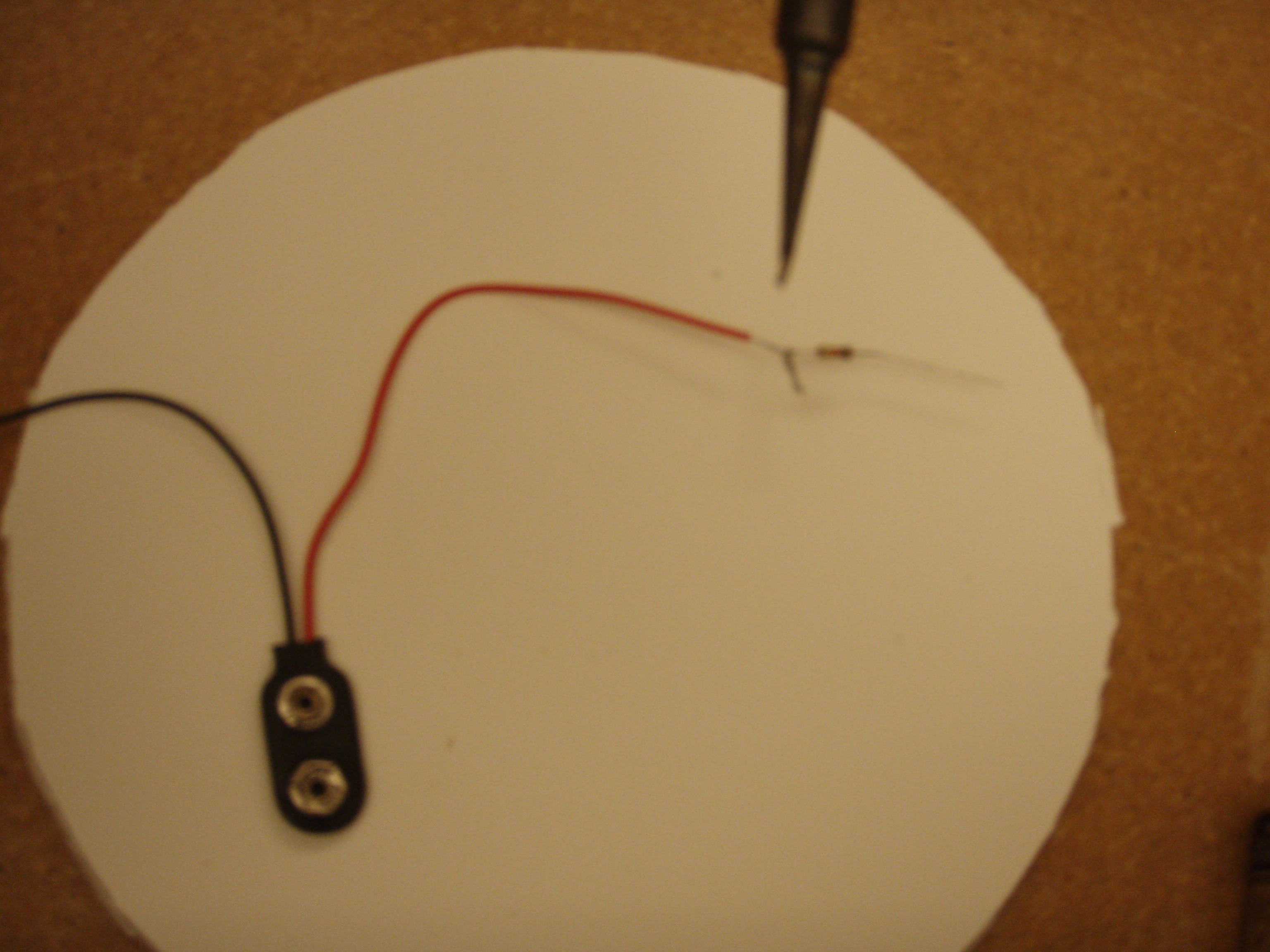

Finally one the same side of the coaxial wire, take the 6 inch blue wire, strip both ends and take one end of it, take the black wire of the 9v mount and the sheilding of the coaxial wire and twist and soder them together. Use the electrometer and test all the wires making sure you have no shorts. Apply heat shrink and hot glue on connection areas and whereever deem neccesary. You should have four of these completed at the end of phase 1.


PHASE 2

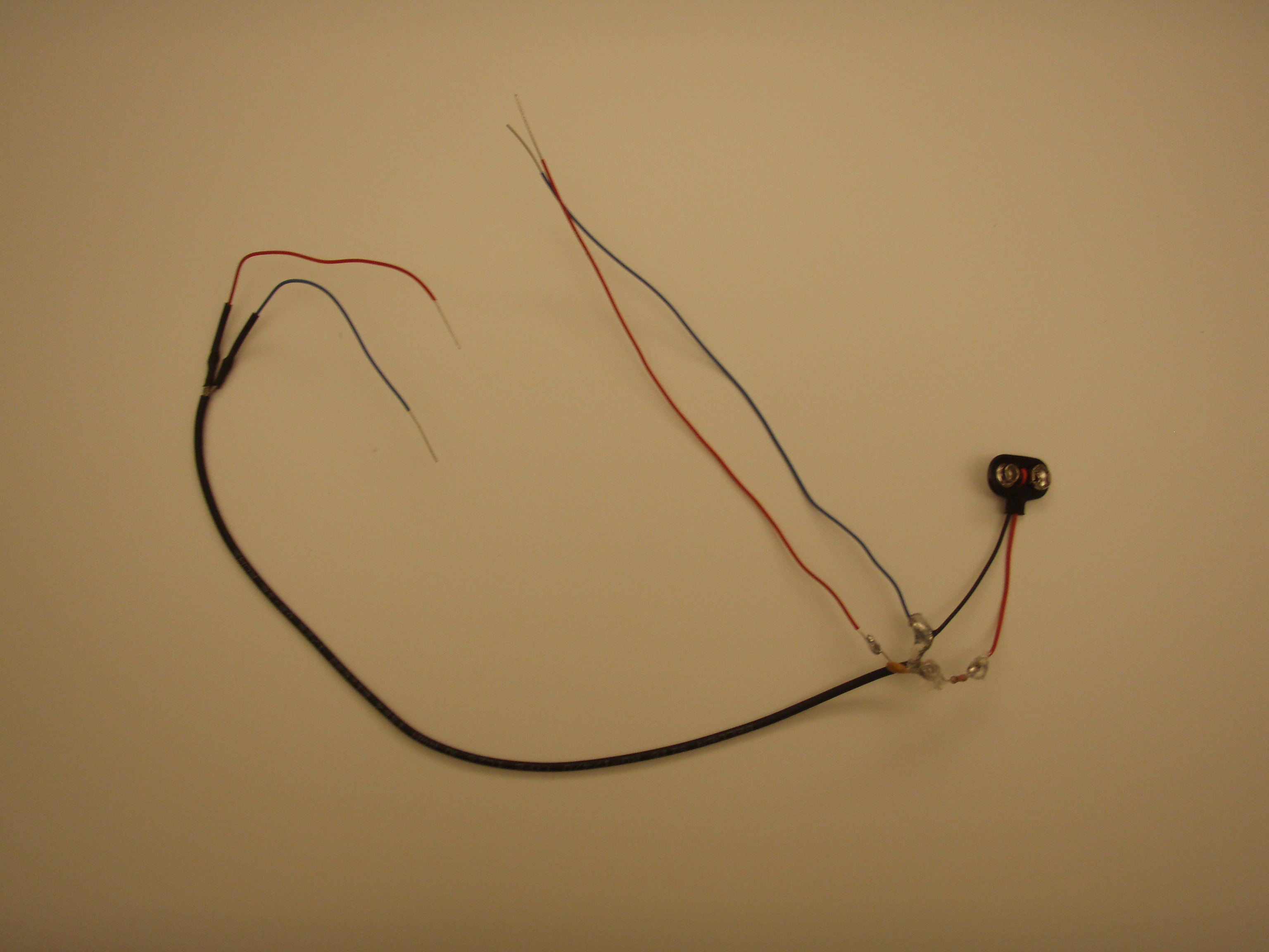
On the end with the 6 inch pair of red and blue wire, soder the free ends into the input head of choice. On the end with the 2 inch pair of red and blue wire, soder the microphone capsule to it (you'll do this 4 times, using 3 figure 8 capsules and one omnidirectional capsule). Use the electrometer and test the connections for the input and the microphone and make sure there are no shorts. Also make sure to test each microphone with a recording programm to make sure it works and gets signal. Apply heat shrink and glue as needed. And phase 2 is complete.


PHASE 3
Materials
Base of some sort (can use and old lamp) I used half a wire spindle and PVC pipe
Finished phase 2 mics (4)
Colored tape (4 colors)
Your 9v batteries (4)

Make your base. I used a wire spindle cut off one end and shoved a short PVC pipe in the hole and kept the PVC pipe stationary in the spindle with washers and zip ties. You basically just need something (an old desk lamp where you take off the head and just use the base and the long flexible neck) to act as your base to which you can put the four ends of your microphone through.

Put a different color tape (one color per mic) one each end of the microphone (one peice of tape on the mic capsule end and one peice of tape on the input head end and make sure to keep track of which 3 mics are the figure eight and which one is the omni). Shove the four microphones into the neck mic capsule end first and organize the battery input end so that the 9v battery mounts are seperated from the inputs (mounts on one side, inputs come out the other end of the base). Arrange the 3 figure eight capsules and the omni to form a tetrahedron. For the figure 8 mics, one is represents the Up - Down (vertical), one is Left Right (horizontal) and the last Back - Front (horizontal perpendicular to the L R mic). Place your omni in opposing direction or near the U D mic). Attach your batteries on the end and you are Golden!


Software
Here are the snippets of code used to convert the A format recorded signal into B format. Please use, fix and help yourself.
Original Code by: Jason Sadural
// (see sndbuf.ck or otf_01.ck for non-insane usage of sndbuf)
SndBuf buf1;
"../data/kick.wav" => buf1.read;
SndBuf buf2;
"../data/kick.wav" => buf2.read;
SndBuf buf3;
"../data/kick.wav" => buf3.read;
SndBuf buf4;
"../data/kick.wav" => buf4.read;
SndBuf buf_out1 => dac;
SndBuf buf_out2 => dac;
SndBuf buf_out3 => dac;
SndBuf buf_out4 => dac;
while( true )
{
// index
int pos;
0 => pos;
// repeat this many times
repeat( buf.samples() )
{
// set next sample
buf1.valueAt( pos ) + buf2.valueAt( pos ) + buf3.valueAt( pos ) +
buf4.valueAt( pos ) => buf_out1.valueAt( pos );
// set next sample
buf1.valueAt( pos ) + buf2.valueAt( pos ) buf3.valueAt( pos ) -
buf4.valueAt( pos ) => buf_out2.valueAt( pos );
// set next sample
buf1.valueAt( pos ) buf2.valueAt( pos ) + buf3.valueAt( pos ) -
buf4.valueAt( pos ) => buf_out3.valueAt( pos );
// set next sample
buf1.valueAt( pos ) - buf2.valueAt( pos ) - buf3.valueAt( pos ) +
buf4.valueAt( pos ) => buf_out4.valueAt( pos );
// increment index
pos++;
// advance time by one samp
1::samp => now;
}
}
Modified Code: By Stephen Henderson
//Encoding of A format Samples into B format
//Formula for Functions attributed to
http://pcfarina.eng.unipr.it/Public/B-format/A2B-conversion/A2B.htm (graduate
research by Angelo Farina case of Soundield Microphone developed by Michael Gerzon, OXFORD
//Concept to use SNDbuf from sndbuf (file read/write/playback) sndbuf and sndbuf.valueat() - random access samples valueat from Jason Sadural
// INPUTS
// (see sndbuf.ck or otf_01.ck for non-insane usage of sndbuf)
//W Omni microphone
SndBuf bufW;
"../data/kick.wav" => bufW.read;
//X Figure Eight Microphone
SndBuf bufXL;
"../data/kick.wav" => bufXL.read;
SndBuf bufXR;
"../data/kick.wav" => bufXR.read;
//Y Figure Eight Microphone
SndBuf bufYU;
"../data/kick.wav" => bufYU.read;
SndBuf bufYD;
"../data/kick.wav" => bufYD.read;
//Z Figure Eight Microphone
SndBuf bufZF;
"../data/kick.wav" => bufZF.read;
SndBuf bufZB;
"../data/kick.wav" => bufZB.read;
//OUTPUTS
SndBuf buf_outW => dac;
SndBuf buf_outX => dac;
SndBuf buf_outY => dac;
SndBuf buf_outZ => dac;
//FUNCTIONS
while( true )
{
// index
int pos;
0 => pos;
// repeat this many times
repeat( buf.samples() )
{
// set W - encoded sample
[bufZF.valueAt( pos ) * bufXL.valueAt( pos ) * bufYU.valueAt( pos )] + [bufZF.valueAt( pos ) * bufXR.valueAt( pos ) * bufYD.valueAt( pos )] + [bufZB.valueAt( pos ) * bufXL.valueAt( pos ) * bufYD.valueAt( pos )] + [bufZB.valueAt( pos ) * bufXR.valueAt( pos ) * bufYU.valueAt( pos )] => buf_outW.valueAt( pos );
// set X - encoded sample
[bufZF.valueAt( pos ) * bufXL.valueAt( pos ) * bufYU.valueAt( pos )] + [bufZF.valueAt( pos ) * bufXR.valueAt( pos ) * bufYD.valueAt( pos )] - [bufZB.valueAt( pos ) * bufXL.valueAt( pos ) * bufYD.valueAt( pos )] - [bufZB.valueAt( pos ) * bufXR.valueAt( pos ) * bufYU.valueAt( pos )] => buf_outX.valueAt( pos );
// set Y - encoded sample
[bufZF.valueAt( pos ) * bufXL.valueAt( pos ) * bufYU.valueAt( pos )] - [bufZF.valueAt( pos ) * bufXR.valueAt( pos ) * bufYD.valueAt( pos )] + [bufZB.valueAt( pos ) * bufXL.valueAt( pos ) * bufYD.valueAt( pos )] - [bufZB.valueAt( pos ) * bufXR.valueAt( pos ) * bufYU.valueAt( pos )] => buf_outY.valueAt( pos );
// set Z - encoded sample
[bufZF.valueAt( pos ) * bufXL.valueAt( pos ) * bufYU.valueAt( pos )] - [bufZF.valueAt( pos ) * bufXR.valueAt( pos ) * bufYD.valueAt( pos )] - [bufZB.valueAt( pos ) * bufXL.valueAt( pos ) * bufYD.valueAt( pos )] + [bufZB.valueAt( pos ) * bufXR.valueAt( pos ) * bufYU.valueAt( pos )] => buf_outZ.valueAt( pos );
// increment index
pos++;
// advance time by one samp
1::samp => now;
}
}
Discussion
Trying to find A way to isolate the samples from two parts of a figure eight microphone. Making sure that the settings - orientation of the microphone tetrahedron does not change and for every computer in respect to the microphone are exactly the same. Can we do this in a different coding language to make it easier? Acutaally finding/coding a platform to which ChucK will come in through recording program and simultaneously run through ChucK for real-time encoding (audacity and ChucK??)
Techniques and Tips
- Closer together the better
- Use of directional microphones instead of figure Eight
Sources
http://pcfarina.eng.unipr.it/Public/B-format/A2B-conversion/A2B.htm
http://pcfarina.eng.unipr.it/Aurora/B-Format_to_UHJ.htm
http://www.core-sound.com/TetraMic/1.php
http://homepage.ntlworld.com/henry01/cheap_soundfield/cheap_soundfield.htm
http://www.michaelgerzonphotos.org.uk/ambisonics.html
http://musica.unq.edu.ar/personales/odiliscia/papers/SBCM-2001.htm
http://gsd.ime.usp.br/sbcm/2001/papers/rOscar_Liscia.pdf
http://www.actlab.utexas.edu/~danh/Soundscapes/Page11.html
http://www.radio.uqam.ca/ambisonic/comparative_recording.html
http://www.soundonsound.com/sos/Oct01/articles/surroundsound3.asp
~Fons Adriaensen
Laboratorio di Acustica ed Elettroacustica, Parma, Italy
fons@kokkinizita.net
5th Linux Audio Conference
TU Berlin, 22. . . 25 March 2007
~Fernando Lopez Lezcano. Talked to him briefly concerning possibilities of homemade ambisonic microphone
~Jason Sadural. Hands on Help session with ChucK coding Wednesday, Dec. 2, 2009
~AMBISONICS SYMPOSIUM 2009
June 25-27, Graz
THE B-FORMAT MICROPHONE REVISED
Johann-Markus Batke
Thomson Corporate Research, Karl-Wiechert-Allee 74, 30625 Hannover, Germany (Jan-Mark.Batke@thomon.net)
http://www.soundonsound.com/sos/oct01/images/surround1b.gif (image acknowledgement)
http://www.veoh.com/browse/videos/category/music/watch/v18845631hTy6ZRnd